Thursday, March 25, 2010
Friday, March 19, 2010
AVR Digital I/O Registers
Each port pin consists of three register bits: DDxn, PORTxn, PINxn.
DDxn bits are accessed at the DDRx I/O address.
PORTxn bits are at the PORTx I/O address.
PINxn bits at the PIN I/O address.
Note:
DDRx is the Data Direction Register. This register sets the data direction of individual pins of port x. A logic level of '1' sets a port pin as output. A logic level of '0' sets a port pin as input.
ex:
PORTx is the Data Register. If you have set any pins on the port as output using the DDRx register you can now control them with this register. A logic level of '1' makes a port pin high. A log level of '0' makes a port pin low.
ex:
PINx is the Input Pin Address Register. If you have set any pins on the port as input using the DDRx register you can now read the status of them with this register.
 ex: Assuming a switch is interfaced to Port A Pin 0 with a pull up resistor...
DDxn bits are accessed at the DDRx I/O address.
PORTxn bits are at the PORTx I/O address.
PINxn bits at the PIN I/O address.
Note:
Each instance of 'x' should be replaced with the port identification letter (A,B,C,D, ect.)
Each instance of 'n' should be replaced with a pin number (0..7)
DDRx is the Data Direction Register. This register sets the data direction of individual pins of port x. A logic level of '1' sets a port pin as output. A logic level of '0' sets a port pin as input.
ex:
DDRB=0b00000001 // Set direction of port B pin 0 as output, all others input
DDRD=0b00100010 // Set direction of port D pin 5 and pin 1 as output, all others input
PORTx is the Data Register. If you have set any pins on the port as output using the DDRx register you can now control them with this register. A logic level of '1' makes a port pin high. A log level of '0' makes a port pin low.
ex:
PORTB=0b00000100 // Make port B pin 2 high, all others low
PORTA=0b00000101 // Make port A pin 2 and pin 0 high, all others low
PINx is the Input Pin Address Register. If you have set any pins on the port as input using the DDRx register you can now read the status of them with this register.
 ex: Assuming a switch is interfaced to Port A Pin 0 with a pull up resistor...
if (PINA & 0b00000001) {
// Switch interfaced to Port A Pin 0 is open
}
else {
// Switch interfaced to Port A Pin 0 is closed
}
Thursday, March 18, 2010
Prototype ATmega644P Breakout Board First Program
Loaded up my first program to my ATmega644P board today. Its just a simple program to set Pin 0 on port B as output and then loop forever toggling the the pin as high and low with a short delay in between.


Board setup and scope output.
The code is not so interesting so I wont bother posting it here. Its nothing that can not be seen in any other beginner tutorials for AVR micros around the net.
I will be doing some experimenting with the Analog-to-digital converter and dual USART ports on the ATmega644P that will probably be a bit more interesting.
Wednesday, March 17, 2010
Programming an ATmega644p with AVR Studio and the AVRISP mkII

ATmega644p
Programmer:
AVRISP mkII
Platform:
Windows 7
Software:
AVR Studio Version 4.18
AVR Studio 4.18 SP2 (build 700)
WinAVR
Pinouts:
pin 10(VCC) and 30(AVCC) are +5v
pin 11 and 31 are GND
pin 9(RESET) pulled high with a 10k Ohm resistor
pin 6(MOSI) to ISP pin 4
pin 7(MISO) to ISP pin 1
pin 8(SCK) to ISP pin 3
pin 9(RESET) to ISP pin 5
Tuesday, March 16, 2010

Monday, March 15, 2010
Sunday, March 14, 2010
5V Fixed Voltage Regulator and Ripple Voltage
I have been experimenting with the common 7805 linear voltage regulator as a power supply.
 To start I simply wired up the regulator with an resistor and led as the load.
 Looking at the output of the regulator on my scope we can see a large ripple voltage of around +/- 1 volt!
I would prefer a nice and clean clean 5 volt output and in order to provide it we need to smooth out the supply voltage. Adding some larger capacitors on both the input and output of the regulator reduces the ripple we see above.
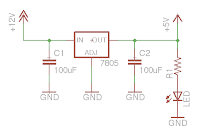 Two 100uF caps are added from input to ground and output to ground.
 The result is a clean 5 volt output.
I picked the two 100uF caps because thats just what I had handy. Intuition tells me that larger caps will take longer to respond to the ripple voltage and that capacitors that are too small will not hold a charge large enough to compensate for the ripple. I do not know is how to determine optimally sized caps.
Also I really did not have a load on the output of the regulator. I am curious of the effect of a larger current draw in the circuit.


I would prefer a nice and clean clean 5 volt output and in order to provide it we need to smooth out the supply voltage. Adding some larger capacitors on both the input and output of the regulator reduces the ripple we see above.


I picked the two 100uF caps because thats just what I had handy. Intuition tells me that larger caps will take longer to respond to the ripple voltage and that capacitors that are too small will not hold a charge large enough to compensate for the ripple. I do not know is how to determine optimally sized caps.
Also I really did not have a load on the output of the regulator. I am curious of the effect of a larger current draw in the circuit.
Thursday, March 11, 2010
SA Improvements Underway
Attending the CIRC Bot Brawl was a great proving ground for SA. Myself and the Mech Warefare participants in attendance learned a lot.
A few things that I observed:
Circuit protection
SA's camera and transponder are unprotected from stray bbs.
Gun Wiring
Wiring is a mess up on the turret. Will need to look into some better wire management.
Turret Mechanical Limits
Turret unable to aim down making it impossible to shoot low mounted targets on close mechs.
Fine Turret Control
My fine turret control needs to be finer. Will make aiming much easier.
Small Camera Image
The camera image on the drivers end is much too small. Needs to be full screen.
Large Step Length
Need a larger gradient on step length. Will make positioning and aiming easier.
Ugly Target Panels
Would like to dress these up to match the robot. Possibly add some Upgrayd Labs logos or some kind of made up paramilitary decal.
CIRC Bot Brawl Recap

On March 6th, 2010 SA and I attended the CIRC Bot Brawl event in Peoria Illinois.
The event was for competitions sponsored by the CIRC group. They had light weight combat robots (1-3 lb I believe), line following, sumo and other typical robot competitions. Between CIRC events Mech Warefare demos were held to gain interest in the competition.
Four mechs were in attendance. Two quads (SA and Issy) along with two Lynxmotion Biped BRAT based mechs. Unfortunately only the two quad mechs were fully functional and able to run a few demo skirmishes. One Biped BRAT was experiencing some electrical interference issues between his own electronics while the other was unable to keep balanced with all the required Mech Warfare gear attached.
Subscribe to:
Posts (Atom)